EP1000
Assignment: Electronics
In this assignment, you will attempt to learn some basic electronics. You have a fantastic online tool to help you with your work and you should learn how to be familiar with it.
The practical session of this assignment is to
- read an article on how to create a LED flasher with a 555 integrated circuit
- test your circuit using a breadboard
- solder your circuit onto a veroboard/stripboard
The skills you will learn are:
- understanding an electronic circuit
- how to test your circuit using a breadboard
- soldering skills
Assignment: Electronics
I have provided approximate timings for you so that you do NOT spend all your time (doing something you like and neglecting other modules!)
| Time | Task |
|---|---|
| 30 min | Watch the Youtube tutorials on TinkerCAD circuits |
| 60 min | Participate and learn basic electronics with OpenLearn |
| 15 min | Read an article on how to create a LED flasher |
| 60 min | Wire up your circuit on a breadboard, and test it |
| 60 min | Solder your circuit on a veroboard/stripboard |
This is a rather longer assignment, however, you have the term break holidays to work though this assignment. Come to the Fablab for advice and help.
Here is a quick guide:
On the laptop:
- Watch the YouTube videos above to get an idea of how TinkerCAD Circuit works and how to use it.
- Familiarize yourself with the common electrical components and try out designing some circuits.
- Go through the OpenLearn course on Basic Electronics.
Practical Session:
This practical assignment walks you through the creation of a simple circuit, simulation using TinkerCAD, verifying your circuit using a breadboard and finally, implementing your circuit using a veroboard/stripboard.
Do NOT attempt to do all parts at once, space them out over the holiday break. The components for this assignment can be obtained in T1442 Fablab EA, upon request.
- Understand how to use Tinkercad
- simple LED, Resistor circuit
- measurements: Voltage, Current
- using a Frequency Generator to flash the LED
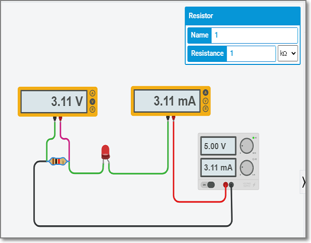
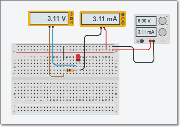
- the sample circuit below shows how Voltage and current readings can be obtained using TinkerCAD.
- implement the circuit using TinkerCAD
- observe the readings by changing the value of R1
- the circuit can be used to verify Ohm’s law
- a voltmeter is used to measure voltage, and must be placed parallel to the component of which the voltage is to be taken
- an ammeter is used to measure current, and must be placed in series with the circuit.

- what value of R must I insert to allow only approximately 5mA of current to flow through the circuit?
- Learn how to use a Breadboard
- Watch Youtube How To Use a Breadboard
- or read SparkFun How to use a Breadboard
- Go to T1442 Fablab EA, transfer your circuit to an actual breadboard (without the meters), verify that it works.

- Alternatively, you could try it on TinkerCAD first!
- Wire up a 555 Timer circuit
- Read the operation of a Astable 555 Timer
We will be using this circuit, with the exception that- Voltage is 5V

- Read the operation of a Astable 555 Timer
-
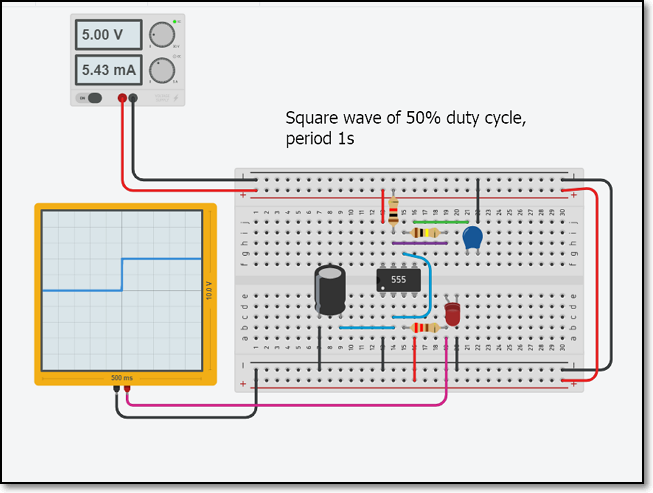
Test the circuit using TinkerCAD and observe the waveform by using an oscilloscope. You should be able to obtain a square wave showing the flashing of the LED on simulation.

- Note: If you change the value of C1, you can change the rate at which the LED flashes.
- Note: If you change the value of C1, you can change the rate at which the LED flashes.
- Try implementing the circuit using an actual breadboard. You can obtain the components from T1442.
If you are stuck, here is a Step-by-step Guide - Wire up an actual circuit using Veroboard/Stripboard
- Read this article: Soldering 555 timer on stripboard
It shows how to implement a 555 Astable circuit on a veroboard. Follow the following steps to complete your assignment - Soldering
- If you are new to soldering, watch the following site/videos first
- Sparkfun How to Solder
- Instructables How to solder
- Youtube How to Solder
- No matter how good you are at soldering, you NEED to watch this 10 STUPID ERRORS To AVOID in Soldering and TIPS
- If you are new to soldering, watch the following site/videos first
- Veroboard
- Implementing your circuit
- Fritzing Tutorial Stripboard
- Dronebot Workshop Breadboarding & Prototyping for Electronics, Arduino & Raspberry Pi
- Read this article: Soldering 555 timer on stripboard
- Implement your 555 circuit on a piece of veroboard. You need to show
- your design/sketch of the Veroboard plan
- your “hero” shots of the completed circuit
- optional: a 15 second video (placed on YouTube) of how your working Astable circuit implementation.
- You can find some help here: Stripboards
- Write up your process in your blog under the title “Electronics Implementation”. You should have
- step-by-step use of TinkerCAD
- implementation of a 555 Timer on breadboard (either virtual/actual)
- 555 Timer soldered on a Veroboard/Stripboard
Graded
This assignment is graded.
For the grade, you have to
- Document your work, showing how to have mastered the breadboard circuit and the stripboard for simple circuit construction
- Write a how-to on creating the stripboard circuit
- Document your errors and success stories
- Have proper photos and “hero-shots”
November 2020