EP1000
Electronics
This is a fast and brief introduction to Electronics. We do not attempt to make you electronics engineers or experts, but you should have enough knowledge to connect up a simple circuit successfully as well as use the circuit to measure or output a result.
Basics
Electricity is the flow of electronics in a closed circuit.
- Voltage is the difference in electrical potential between two points, measured in Volts.
- Current is the rate of flow of electrical charge past a point. Current is measured in Amps.
- Electrical resistance (or Resistance) of an object is a measure of the opposition to the flow of electric current. Resistance is measured in Ohms
- In order for current to flow, the circuit must be closed.
There are two types of electric currents
- AC (Alternating current) where the voltage moves from positive to negative values, alternating in time,
- Home electricity is AC - 230V, 13~15 Amp
- A bicycle dynamo is AC - 5-9V, 0.1~0.5 Amp (depending on how fast you peddle!)
- DC (Direct current) where the voltage potential is at a fixed value (either positive or negative).
- AA battery source is DC, 1.5V, 500mA Ref: Energizer E91
- 18650 LiON battery (used in most laptops, mobile battery packs) is DC 3.7V, 1~2A (You can discharge more, but the batteries catch fire!)
- We will mainly work with DC currents and voltages.
Two important Electrical Laws
Ohm’s Law
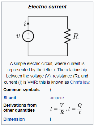
Ohm’s law states that Voltage = Current * Resistance, or written as
- Voltage = Current x Resistance
- Current = Voltage / Resistance
- Resistance = Voltage / Current
Calculating resistance in a circuit
- Resistors in series, R = R1 + R2
- Resistors in parallel, R = 1/R1 + 1/R2
Kirchoff’s first law (the current law)
- At any junction, or node, in an electrical circuit, the sum of the currents flowing into the node is the sum of the currents flowing out of a node.
Kirchoff’s second law (the loop/mesh law)
- When the direction is taken into account, the sum of the potential differences in any closed circuit is zero.
Electrical Components
Electrical components are broken down into 3 types
- Insulators - prevents current from following
- Conductors - allows current to flow
- Semiconductors - allows current to flow only if some electrical conditions are met.
Common Electrical components
- Wires
- Wires are conductors, usually with very, very low resistance. Usually made up of copper with an insulator on the outside.
- Wires are used for connections and creation of closed circuits.
- The thickness of the wire is measured using AWG (American Wire Gauge). The larger the number, the smaller the diameter.
- Switches
- An electrical component that breaks a circuit when manually operated. Usually made up of two contacts separated by a conductor. When the conductor is closed, the circuit is completed.
- Common types of switches
- SPST - Single Pole Single Throw
- Push-to-make
- Push-to-break
- Normally-closed, throw switch to break circuit
- Resistors
- an electrical component which has made to have a fixed resistance to current.
- resistors are [color coded(https://www.digikey.com/en/resources/conversion-calculators/conversion-calculator-resistor-color-code-4-band) so that you can identify them
- besides, resistance values, resistors come in different power ratings to handle the amount of current that can safely flow through.
- Capacitors
- electronic components that can store charge.
- made up of two sheets/plate of conductors separated by an insulator/dielectric, charge is accumulated on each plate
- used as filters
- not essential to our fabrication course
- Diodes
- semi-conductors that allow current to flow ONLY in one direction.
- used for filtering AC
- LED (Light Emmi ting Diodes) are special diodes which give off light when the current flows in the correct direction.
- Transistors & MOSFETs
- semi-conductors that allow current to flow provided an electrical condition is met on one of the pins.
- can be used as amplifiers (non-saturation) or switches (saturation)
- we shall use transistors mainly as electrical switches.
- Integrated circuits
- devices which are miniaturized electrical circuits. Each IC can contain thousands of other electrical components configured in a particular circuit(c)
- our modern day building blocks
Measurements
It is common for electrical components to have a prefix (e.g. Kilo) placed in front of the value. The following table shows the significance of each of the terms as applied to resistance, voltages, currents and other electrical values.
| Prefix | Symbol | Base 10 | Decimal |
|---|---|---|---|
| mega | M | 10^6 | 1 000 000 |
| kilo | K | 10^3 | 1 000 |
| 10^0 | 1 | ||
| mili | m | 10^-3 | 0.001 |
| micro | μ | 10^-6 | 0.0000001 |
| nano | n | 10^-9 | 0.000000001 |
| pico | p | 10^-12 | 0.000000000001 |
Learning Electronics
Watch this Simple Guide to Electronic Components to help you identify the physical electrical components that you may encounter.
A good and simple introduction to electronics can be found at the Open University site OpenLearn - An Introduction to Electronics. After finishing this very short course you may also print out a certificate of attendance!
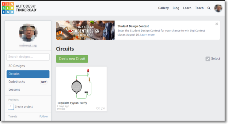
However, most students like the harder and more practical method of learning by doing, as such you have the site TinkerCAD by Autodesk. You can sign in with your Autodesk account.
Under TinkerCAD, you have Circuits which allows you to design, tinker and test your circuits before you implement them physically. This tool greatly enhances the learning experience in Electronics.
References:
- OpenUniversity OpenLearn An Introduction to Electronics
- Sparkfun tutorials
- TinkerCAD
- EngCS Youtube Videos:
- Dennis Humphrey Making series and parallel circuits using Tinkercad
Assignment: Electronics
In this assignment, you will attempt to learn some basic electronics. You have a fantastic online tool to help you with your work and you should learn how to be familiar with it.
The practical session of this assignment is to
- read an article on how to create a LED flasher with a 555 integrated circuit
- test your circuit using a breadboard
- solder your circuit onto a veroboard/stripboard
The skills you will learn are:
- understanding an electronic circuit
- how to test your circuit using a breadboard
- soldering skills
Assignment: Electronics
November 2020

